This method allows you to create a custom effects filter for raster images.
Parameters
| Name | Explanation |
|---|---|
| Points | An array of x and y coordinate values defining
points of a polygonal area on the image. (in pixels) In C++Builder, the size of the Points array is given by Points_Size - 1 |
| Matrix | 9x9 matrix (an array of 81 items ranging from 0 to
80). In C++Builder, pass the size of the Matrix_Size array as 80 |
| ADiv | The division factor |
| Level | The bias factor (from 0 to 255, as this factor increases, the color becomes brighter) |
| Red | To process the red plane, set toTrue (nonzero), otherwise set to False (0) |
| Green | To process the green plane, set toTrue (nonzero), otherwise set to False (0) |
| Blue | To process the blue plane, set toTrue (nonzero), otherwise set to False (0) |
Return Value
Returns True if successful, otherwise returns False.
Explanation
The CustomFilter method allows you to create a custom effects filter for raster images. An effects filter alters each pixel's color based on its current color and the colors of any neighboring pixels. (See the explanation of the filter matrix below.)
To execute the CustomFilter method, set the image handle of the image in the ImageHandle property or the Layer(LayerNo).ImageHandle property. The CustomFilter method supports 8-bit grayscale, 16, 24, and 32 bit images.
Before executing the CustomFilter method, you must set the area on the image that will be affected. There are 4 ways to do this.
- To use a mask image, set the SelectMode property to vikEffectMask. Set the mask image handle in the MaskImageHandle property
- To process the total image, set the SelectMode property to vikEffectAll.
- To process the polygonal area on the image, set the SelectMode property to vikEffectPolygon. Select the polygon by setting the appropriate coordinate values for the points of the polygon in the Points array. The number of points defining the polygon must be 3 or more.
- To process an elliptical area on the image, set the SelectMode property to vikEffectEllipse. Select the ellipse by setting the appropriate values for the bounding rectangle in the RectLeft, RectTop, RectRight, and RectBottom properties
When the SelectMode property is set to vikEffectPolygon or vikEffectEllipse, the InOut property should be set. When the SelectMode property is set to values other than vikEffectPolygon, please set the Points parameter to a dummy array or to NULL. When processing a grayscale image the Red, Green and Blue parameter values are disabled. (dummy values).
If successful, the resulting raster image data is set in the LayerNo property (the ImageHandle property or the Layer(LayerNo).ImageHandle property. If unsuccessful, 0 is returned.
When the Caption, Message, and ButtonName properties are blank, the progress dialog box will not be displayed. When the progress dialog box is displayed, the percentage that the processing has completed will be shown in the dialog box.
The filter consists of an array of coefficients called a filter
matrix. A filter processes an image on a pixel-by-pixel basis. Each
pixel's color value is multiplied by the coefficient in the matrix
center, and any pixels within the matrix are multiplied by the
corresponding coefficients. The sum of the products becomes the
target pixel's new value. To make the filter matrix, it is
necessary to create an array containing 80 elements and set the
appropriate coefficient values in the array elements. The formula
used to calculate the target pixel's value is given below:
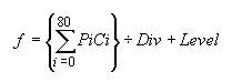
Where F is the output value of the target pixel, Pi is a pixel in
the grid, and Ci is a coefficient in the matrix. Div is the
division factor which allows you to achieve effects that would
otherwise require decimal coefficients. Level is a bias factor. You
use the bias to shift the value of each pixel by a fixed amount. As
the bias factor increases, the resultant color is brighter. Bias
adjustments are particularly useful for creating embossing
effects.
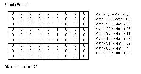
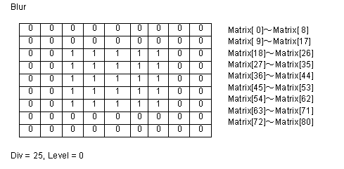
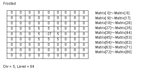
Some sample matrix are given below:
Differences from the ImageKit 7/8/9/10 ActiveX
The parameters x, y have been changed to type TPoint
In Delphi, it is not necessary to pass the size of the array of x,
y points.
The Matrix parameter has been changed to an array.
In C++Builder, a parameter for size of the Matrix array has been
added.